Design Criteria for Vertical Equipment
1.
Wind Load:
Basic diameter = diameter O.D. + 2 (shell thickness + insulation),
effective projected area = height x I.F. x basic
diameter.
For shape factor, rough surface is used.
Gust factor > 2.0, for slender vessel, vortex shedding shall be
considered.
Intensification Factor (I.F.):
Diameter <= 760 mm, I.F. = 1.50
Diameter 900 to 1350 mm, I.F. = 1.40
Diameter 1370 to 1960 mm, I.F. = 1.30
Diameter 1980 to 2570 mm, I.F. = 1.20
Diameter >= 2590 mm, I.F. = 1.18
For tall vessel (>= 30 m), the strong wind 1/100
year wind pressure is used.
2. Load Combinations:
Empty Load (Erection Load) + Wind (Seismic)
Operating Load + Temperature + Live Load
Operating Load + Wind (Seismic)
Operating Load + Temperature + Wind (Seismic)
Operating Load + Temperature + Live Load + Wind (Seismic)
Test Load
Test + 0.5 Wind (Seismic)
3. Anchor Bolts Design:
Maximum tension = 4.M / (N x BC) - W / N.
M - maximum overturning moment at base of vessel.
N - number of bolts.
BC - diameter of bolt circle.
W - weight of vessel.
The dead load factor for overturning is 0.85.
Normally, for bearing type bolt shear capacity, only half of
anchors actually transfer the shear load.
If anchor bolt in tension and concrete pull-out capacity is not
enough, vertical dowels are required to transfer tensile forces to foundations,
for development length of rebars , check ACI351.3R 4.2.1
4. Pedestal Design:
Pedestal shall be designed as cantilever columns, k = 2.0.
The pedestal size <= 1.5m, square pedestal may be economical,
normally, octagonal shape is used.
Top of pedestal is 300 above grade.
Face to face pedestal size:
Bolt circle + 200 mm
Bolt circle + 8 x bolt diameters.
Bolt circle + Sleeve diameter + 150 mm
Diameter of base plate + 100 mm.
Maximum dowel tension = 4.Mu / (n x BD) - Wu /
n.
Mu - maximum overturning moment at base of
pedestal.
n - number of bars.
BD - diameter of bar circle.
Wu - Factored vertical load (factor =0.85).
Minimum reinforcement:
Octagon <= 2.7 m, 16 - 25M vertical with 10M ties at
400 mm maximum.
Octagon 2.75 to 3.7m, 24 - 20M vertical with 15M ties
at 250 mm maximum.
Octagon > 3.7 m, 32 - 20M vertical with 15M ties at
250 mm maximum.
Pedestal over 1.8m shall have a mesh at the top, 10M at 200mm
spacing in both direction, minimum.
5. Footing Design:
The footing size < 1.5m, square footing may be economical,
normally, octagonal shape is used.
Minimum thickness is 300 mm.
Minimum rebars 15M @ 300 c/c for top and bottom both direction.
Top of footing shall be minimum 300 mm above grade.
6. Normally, the stability ratio is = 1.5 for sliding and overturning, but for
tall vessel (>= 30m), 2.0 is used.
7. Soil Bearing:
Allowable soil bearing pressure may be increased 33% for wind or
seismic loading.
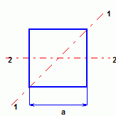
Bearing pressure for square footing:
For axis 1-1:
B.P.max = [ 1 + 8.485e / a] P /a2
B.P.min = [ 1 - 8.485e / a] P /a2
For axis 2-2:
e <= a/6 B.P.max =
P/a [1 + 6e/a] B.P.min = P/a [1 - 6e/a]
e > a/6 B.P. = 2P / [3a(a/2
- e)]
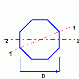
Bearing pressure for octagonal footing:
B.P.max = 1.2[ 1+ 8.19 e/D] P/ D2
B.P.min = 1.2[ 1- 8.19 e/D] P/ D2
8. Foundamental Frequency:
For a vessel with constant wall thickness, constant diameter, and a
fixed base, the natural frequencies are those for a cantilever beam:
ni = ki / H2[ E.I /M]0.5
ni = frequency of mode i (Hertz)
Ki = constant
= 0.56 for mode 1
= 3.51 for mode 2
= 9.82 for mode 3
= 19.2 for mode 4
H = height of vessel(m)
E = Modulus of elasticity (pa)
I = moment of inertia of vessel(m4),
I = p.d3.t / 8
M = mass of vessel per unit length. (kg per meter or
N.s2 /m per meter, = N / 9.81)
d = inside vessel diameter (m)
t = vessel wall thickness (m)
9. Tall vessel structural damping:
It depends not only on the vessel itself, but also on the vessel
soil-structure interaction.
Concrete vessel: 0.0150 – 0.025
Steel vessel: 0.005 – 0.015
Unlined steel stack: 0.0016 – 0.006
Gunite-lined steel stack: 0.003 – 0.012
Concrete chimney: 0.004 – 0.020
The lower values are appropriate for foundation on rock
or piles, average values are appropriate for foundations on compacted soil,
higher values are appropriate for vessels supported by
elevated structures or soft soils.
10. Period for seismic design
Reference: ASCE Guilde for Seismic Evaluation and
Design of Petrochemical Facilities 4.A-4
T = 7.78x10⁻⁶ (H / D)2 [ 12 W. D / t ]0.5
H - vessel height (ft.)
W - vessel linear weight (lb/ft.)
t - vessel shell thickness (in.)
D - vessel shell outside diameter (ft.)
T - period (sec.)